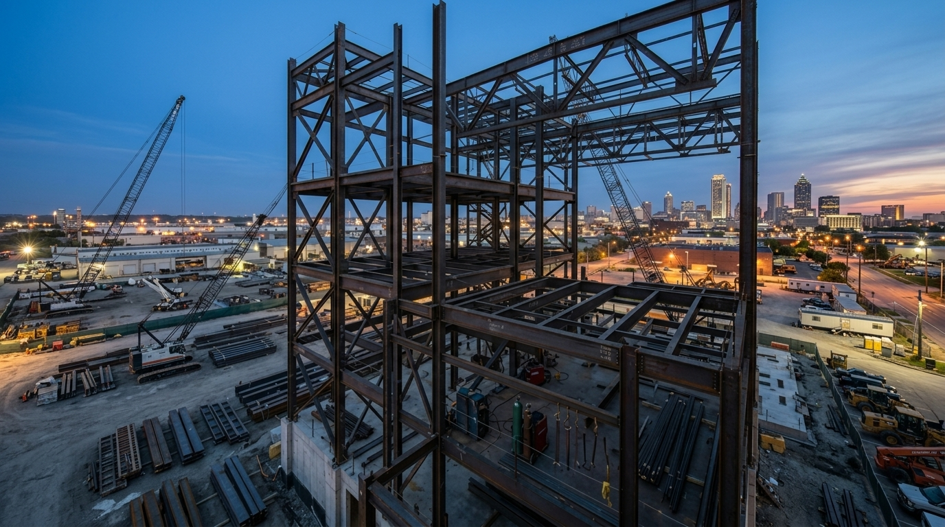


A steel connection joins two or more members and transfers load between them. Almost every connection falls into one of two families. Simple (shear) connections carry the beam’s end reaction and let the joint rotate. Moment connections hold the joint rigid and carry bending as well as shear. Bracing connections, column splices and base plates round out the list.
For an estimator, the type sets the material and the labor. A shear tab is a plate, a few bolts and two short fillet welds. A welded moment connection can mean groove welds, backing bars, stiffeners and inspection. This guide covers each common type, how to recognize it on structural drawings, and what to count. For the full estimating process, see our steel estimating guide.
Shear and Moment Connections Are the First Split
AISC 360, the Specification for Structural Steel Buildings, sorts connections into simple, fully restrained (FR) moment, and partially restrained (PR) moment. Most beam ends on a typical job are simple shear connections. Moment connections show up where the engineer needs a rigid frame for wind or seismic load, or to support a cantilever. Sort every beam end into shear or moment before you count anything else.
Shear Connections Carry the Beam Reaction With Little Material
The AISC Steel Construction Manual covers several standard simple shear connections. These four are the ones you will count most often.
Shear Tab (Single Plate)
A shear tab is a single plate shop welded to the supporting member, a column flange or a girder web. The beam web is field bolted to the plate. It is the most common shear connection in North American framing because the shop does the welding and the field crew only bolts.
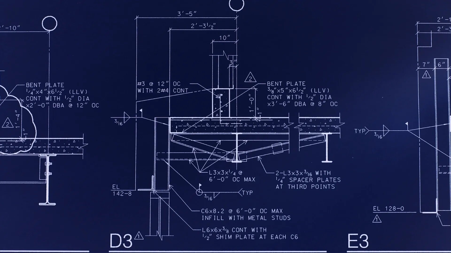
On drawings, shear tabs are rarely drawn at each beam. Look for a typical detail on the connection details sheet and a general note on how unshown connections are to be designed. Some engineers add a schedule that sets bolt rows by beam depth.
For the takeoff, count per beam end: one plate, the bolts, the holes in the beam web, and the fillet weld on both sides of the plate. Extended shear tabs, used at column webs or for clearance, are longer and heavier, so price them separately.
Double Angle (Clip Angle)
A double angle connection uses two angles, one on each side of the beam web. The angles are usually shop bolted or shop welded to the beam, then field bolted to the support. Some shops call these clip angles. A single angle version exists for lighter reactions or tight access.
On drawings, look for “2L” callouts in the typical details (for example, a pair of angles with a size and length). For the takeoff, count two angles per end, their length, the bolts through the beam web, the bolts through the outstanding legs, and holes in the angles, beam and support.
Seated Connections
A seated connection supports the beam’s bottom flange on a seat angle, with a top or side angle for stability. A stiffened seat adds a vertical plate or tee under the seat for heavier reactions. Seats are common at column webs and where erection access is tight.
On drawings, seats show up in section details as an angle under the bottom flange. Count the seat angle, top angle, any stiffener, and the bolts or welds.
End Plate Shear Connections
A shear end plate is shop welded across the end of the beam web and field bolted to the support. It needs an accurate beam cut length, since there is little room to adjust in the field. On drawings, it appears as a “PL” at the beam end in the typical details. Count one plate per end, the weld along both sides of the web, the bolts, and the holes in the support.
Moment Connections Carry the Most Labor Per Joint
On framing plans, engineers commonly mark moment connections with a symbol at the beam end, such as a small filled triangle or flag. The symbol varies, so check the legend. Some plans also note the design moment at the beam end.
Directly Welded Flange
The beam flanges are welded straight to the column flange with complete joint penetration (CJP) groove welds, usually in the field, and the web is bolted to a shear tab. Count the CJP weld length, backing bars, weld access holes, the shear tab and bolts, and inspection. Check the column for continuity plates (stiffeners in line with the beam flanges) and web doubler plates.
Flange Plated
Plates are shop welded to the column flange, then bolted or welded to the beam flanges in the field. Count two flange plates, the shop welds, the field bolts and flange holes, plus the web connection.
Extended End Plate
A thick plate is shop welded to the beam end and extends past one or both beam flanges. It is field bolted to the column flange with pretensioned high-strength bolts. Count the plate, the shop welds (often groove welds at the flanges), the bolts, the matching holes in the column flange, and any column stiffeners.
Bracing Connections Are Built Around Gusset Plates
Braced frames resist lateral load through diagonal members. The brace ends connect through gusset plates at beam-to-column joints, or at beam midspan in chevron (inverted V) bracing. Braces are often HSS slotted over the gusset, angles, WTs or wide flanges.
On drawings, look for bracing elevations, which show brace size, layout and often the design force. Gusset details are usually typical. Count the gusset plates (they are often irregular, so plan for the rectangular plate you buy and the drop), brace end slots, reinforcing plates, welds and bolts.
Column Splices and Base Plates Sit Outside the Framing Plan
Column splices join column lengths, usually a few feet above a floor for erection access. They use flange and web plates, fillers when the column depth changes, or a butt plate between sizes. Find them on column schedules and the typical splice detail. Count the plates, fillers, bolts, welds and the extra column piece.
Base plates connect the column to the foundation. Look for a base plate schedule or column schedule. Count the plate, the weld around the column, the oversized anchor rod holes, plate washers, leveling nuts, and anchor rods and templates if they are in your scope.
Beam-to-Girder and Beam-to-Column Connections Need Different Prep
The same shear tab costs different amounts depending on what it frames into.
A beam-to-girder connection usually has both top flanges at the same elevation. The filler beam needs a top flange cope to clear the girder flange, and a double cope if the depths are close. Count each cope.
At a column flange, the connection is simple. At a column web, it has to fit between the flanges, often with an extended shear tab or a coped beam. Skewed beams need bent or skewed plates, and HSS columns need plates welded to the tube wall. Count by condition, not as one generic “shear connection.”
Bolted vs Welded Connections Change the Shop and Field Labor
Most North American fabricators prefer to weld in the shop and bolt in the field. The drawings and specifications tell you which bolts and welds you are pricing.
Bolts: Snug-Tight, Pretensioned and Slip-Critical
In a bearing-type connection, the bolts carry load by bearing against the sides of the holes. Many shear connections are snug-tight: the plies are drawn together but the bolts are not pretensioned. Pretensioned bolts are tightened by turn-of-nut, calibrated wrench, twist-off tension-control bolts or direct tension indicators.
A slip-critical connection relies on friction between the clamped surfaces, so the faying surfaces need a specified condition, which can mean masking paint. Check the notes and specifications for bolt grade (ASTM F3125 Grade A325 or A490), diameter and slip-critical locations. Count bolts by diameter, length, grade and type, and add the masking labor.
Welds: Fillet, CJP and PJP
A fillet weld sits in the corner between two pieces, is sized by its leg, and is the most common connection weld. A CJP groove weld fuses the full thickness of the joined part, usually with joint prep, backing and often ultrasonic testing. A PJP groove weld fuses part of the thickness.
Weld symbols follow AWS A2.4: a triangle means fillet, a flag means field weld, and a circle means all around. Count weld length by size and type, and never price CJP at the fillet rate.
Steel Connection Types Summary Table
| Connection type | Typical use | How to spot it on drawings | Takeoff items to count |
|---|---|---|---|
| Shear tab (single plate) | Beam to girder or column flange | Typical detail, general notes, bolt-row schedule | Plate, bolts, web holes, fillet weld both sides, copes |
| Double angle (clip angle) | Beam to girder or column | “2L” callouts in typical details | Two angles per end, bolts both legs, holes |
| Seated | Column webs, tight access | Angle under bottom flange in sections | Seat angle, top angle, stiffener, bolts or welds |
| Shear end plate | Beam to column or girder | “PL” at beam end in typical details | End plate, web welds, bolts, support holes |
| Directly welded flange moment | Rigid frames | Moment symbol on plan, CJP weld symbols | CJP length, backing bars, access holes, shear tab, stiffeners, inspection |
| Flange plated moment | Rigid frames | Moment symbol, flange plate detail | Two flange plates, shop welds, field bolts, web connection |
| Extended end plate moment | Rigid frames | Moment symbol, end plate detail | End plate, groove or fillet welds, pretensioned bolts, stiffeners |
| Bracing (gusset) | Braced frames | Bracing elevations, gusset details | Gussets and drop, brace slots, reinforcing plates, welds, bolts |
| Column splice | Multi-tier columns | Column schedule, splice detail | Splice plates, fillers, bolts, welds |
| Base plate | Column to foundation | Base plate or column schedule | Plate, weld, anchor rod holes, washers, anchor rods if in scope |
Why Connection Material Is Where Takeoffs Go Wrong
Main members are drawn on the plans with sizes and lengths. Connections are spread across typical details, notes, schedules and sections, and many are not drawn at all. Our post on where connection takeoff errors occur covers the patterns in depth, and Connection Identification: A Systematic Approach walks through a categorizing framework.
Three causes repeat:
- Miscounts. Every beam has two ends, and each end has its own condition. Skipping a skewed end, an HSS column or a cope adds up across a job.
- Connections designed by others. The AISC Code of Standard Practice describes how connection design can stay with the engineer of record or be delegated to a licensed engineer working for the fabricator. When it is delegated, you price the connection engineering and carry the risk of heavier connections, stiffeners and doublers the drawings do not show yet.
- Percentage allowances. Many shops carry connection material as a flat percentage of main member weight. That can work on repetitive gravity framing but falls apart on moment frames, bracing-heavy jobs and HSS framing. Labor follows the count and type of connections more than the weight.
Practical Checks Before the Bid Goes Out
- Read the general notes and typical details before counting a single connection.
- Check the legend for the moment symbol, then mark every moment end.
- Compare your connection count to the beam count times two.
- Count copes, skews and HSS conditions as separate line items.
- Pull bolt grade, diameter and slip-critical requirements from the specifications.
- Carry a line for stiffeners and doublers when connection design is delegated, and state the assumption.
- Review bracing elevations and column schedules for gussets, splices and base plates.
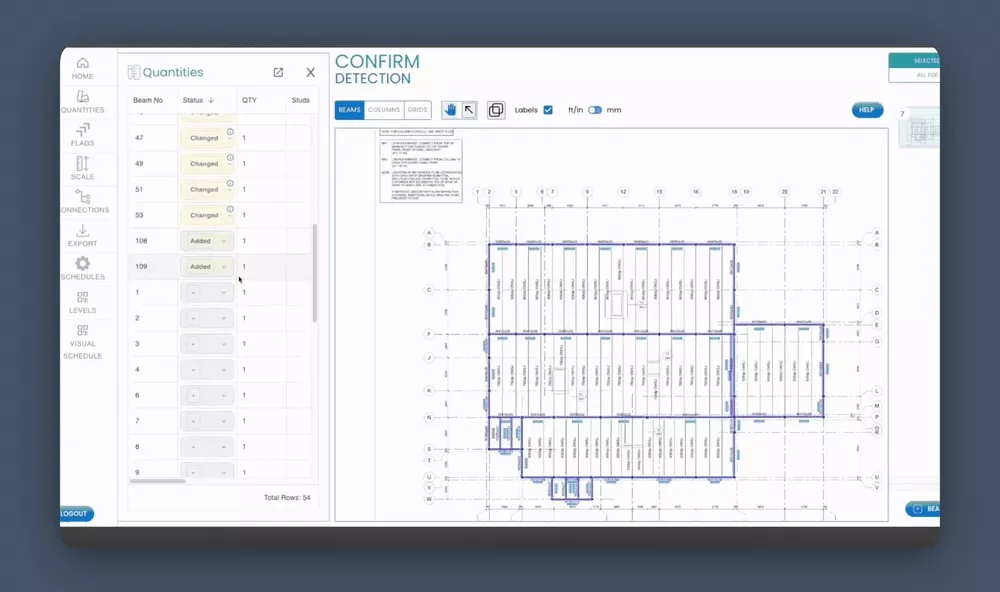
This is the work SketchDeck is built to support. Our steel takeoff software analyzes connections across the drawing set: framing conditions, moments, copes and holes. Each beam end gets a framing code, such as beam to beam, beam to column flange, skewed or HSS, which you map to your own labor codes and man-hours. You add connection material in the same takeoff, and anything unclear is flagged for your review. SketchDeck doesn’t price your labor, so your numbers stay yours. See how fabricators use it in our customer stories.
Frequently asked questions
What is a shear tab connection?
A shear tab is a single steel plate shop welded to a column or girder, with the beam web field bolted to it. It carries the beam’s end reaction and is the most common simple shear connection in North American steel framing.
What is the difference between a shear and a moment connection?
A shear connection carries the beam’s vertical reaction and lets the joint rotate. A moment connection holds the joint rigid and carries bending as well as shear. Moment connections use more material, more welding and more labor per joint.
How do you estimate steel connection material?
Sort every beam end by connection type and condition, then count the plates, angles, bolts, weld length, copes and holes for each. Use the typical details, notes and schedules to fill in what the plans do not show. Counting by type is more reliable than a flat percentage of main member weight.
What does “connections designed by others” mean for the estimate?
It means the engineer of record has not fully designed the connections, and design is often delegated to the fabricator’s engineer. Include the connection engineering cost, carry an allowance for stiffeners and doublers, and list your assumptions in the bid.